Using a Jack Border (Bricscad Users)
A Jack Border is used in VidCAD drawings to organize the layout of multiple jack symbols. When documenting a large number of jack connections you can use a Jack Border to group them together.
The steps below will show you how to create a Jack Border.
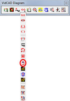
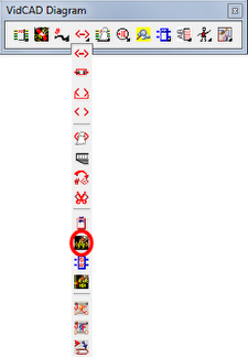
1. Select “Jack Border” from the Jacks Flyout of the VidCAD toolbar.
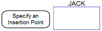
2. The command line will prompt you to specify an insertion point on your drawing. Click on the location you want to place the Jack Border.
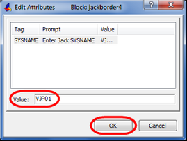
3. In the Value field of the Edit Attributes window, type in a Jack System name then press “OK.”
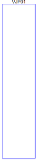
4. The jack border should now display on your drawing.

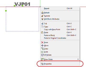
5. Select the jack border then right click and select "Properties."
6. Scroll down the Properties bar and Locate the Distance 1 field that control the height of the border.
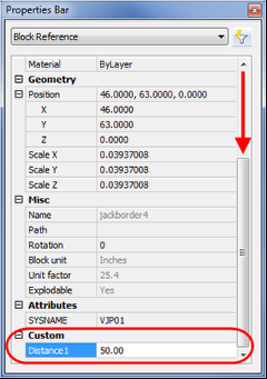
7. Change the value of Distance to 50 then click on another cell in the properties bar. The jack border should immediately increase in size.
8. The value of 50 may be too large or small depending on your situation. Continue editing the value of Distance1 until you find a sizew that works best with your drawing.
9. Move the Jack Border to an existing series of Jack symbols or draw new jack symbols into the Jack Border.
10. As an option to clean up the look of information in the Jack Border you can turn off the Jack Sysname on the jack symbols. To do this, select the “Jack Sysname Off” command from the Jacks flyout of the VidCAD toolbar.
11. The Jack Sysnames on the jack symbols should now be turned off.
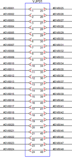
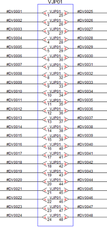
12. The image below shows the use of a Jack Border in conjunction with Jack Sysname off.