Using a Jack Border (AutoCAD Users)
A jack border is used in VidCAD drawings to organize the layout of multiple jack symbols. When documenting a large number of jack connections you can use a jack border to group them together.
The steps below will show you how to create a jack border.
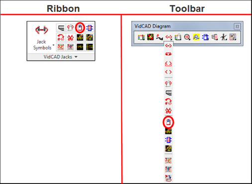
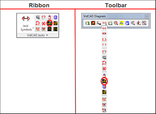
1. Select “Jack Border” from the VidCAD Jacks ribbon or toolbar.
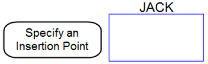
2. The command line will prompt you to specify an insertion point on your drawing. Click on the location you want to place the Jack Border.
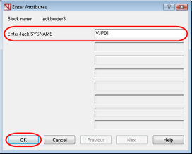
3. In the “Enter Attributes” window, type in a Jack Sysname then press “OK.”
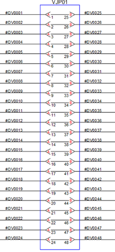
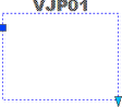
4. The jack border should now display on your drawing.

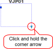
5. Click anywhere on the jack border to select it. You should see a grip and an arrows appear.
6. Click and hold the arrow at the bottom left corner of the Jack Border then drag your mouse down to stretch the block.
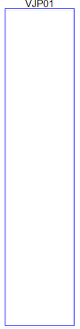
7. Press “Esc” and your jack border should now appear with the desired length.
8. Move the jack border to an existing series of jack symbols or draw new jack symbols into the jack border.
9. As an option to clean up the look of information in the jack border, you can turn off the jack Sysname on the jack symbols. To do this, select the “Jack Sysname Off” command from the VidCAD Jacks ribbon or toolbar.
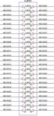
10. The jack Sysnames on the jack symbols should now be turned off.
11. The image below shows the use of a jack border in conjunction with jack Sysname off.