Creating Bulkhead Panels
A bulkhead panel is used to define a pass-through devise such as a wall plate, ceiling panel, floor panel or rack termination panel.
The following steps will guide you through creating a 2X3 wall plate defined as a bulkhead jack panel. The top row of this plate will have three RJ45 connectors. The bottom row will have two BNC connectors and one XLR connector.
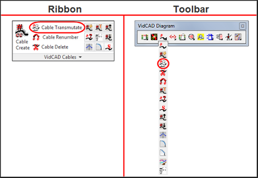
1. Select “Phantom Cable Transmutate” from the VidCAD Cables ribbon or toolbar.
2. Select the Jack symbol from the Phantom Cable Transmutate window.
3. Select “New” in the Select Jack window.
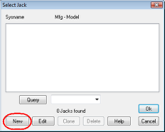
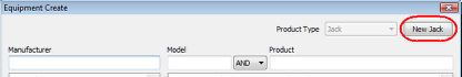
4. The Equipment Create window displays available jack panels that can be added to a project. To create a custom bulkhead panel select “New Jack.”
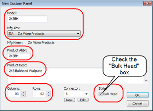
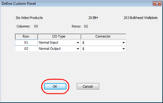
5. In the New Custom Panel window, enter the model name you wish to create, the MFG you wish to use and all other fields you see circled below. Be sure to check the “Bulk Head” option as well.
Note: The connectors for this bulkhead panel will be redefined later.
6. After all descriptions are entered, select “OK.”
7. Select “OK” in the Define Custom Panel window.
Note: The I/O type will be redefined later.
Note: The 2X3BH panel is now part of the product library and can be added to a project
8. You are now returned to the Equipment Create window.
9. Enter the Manufacturer and Model of the custom panel you created.
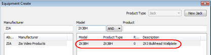
10. Select the 2X3BH then select “Ok.”
11. Modify the Product Abbreviation and Number to form your desired Sysname in the Select System Name window.
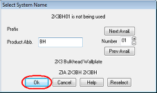
12. Select “Ok.”
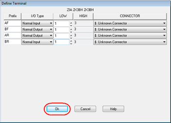
13. Select “Ok” in the Define Terminal window.
Note: The definition of the panel will be redefined later.
14. The jack panel is now created and is part of a project. Now the definition of the panel can be modified.
15. Select the Jack symbol from the Phantom Cable Transmutate window.
16. Select the jack you want to edit.
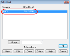
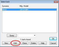
17. Select “Edit” in the Select Jack window.
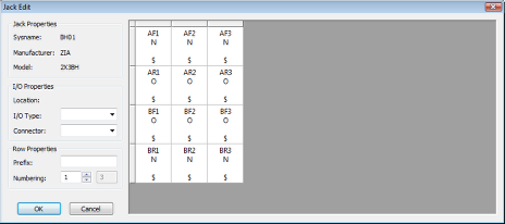
18. The Jack Edit window now displays.
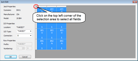
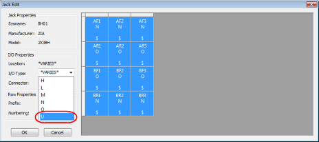
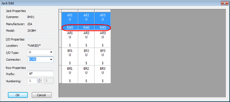
19. Click on the top left corner of the selection area to select all jack positions.
20. After all of the fields are selected, select "U" (Open) as the I/O type for all positions.
Note: If you hover over an I/O type letter, you will see a tooltip with the definition.
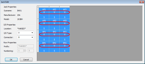
21. All positions should now be defined as Open.
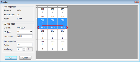
22. Select all positions on the front of Row A.
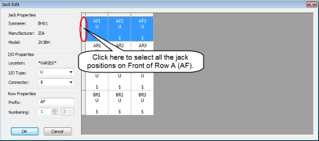
23. Change the connector for the selected positions to “RJ45.”
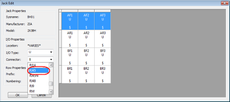
24. Verify the new connector information displays for all selected positions.
25. Repeat steps 22-24 to define the connectors for the rear of Row A (AR).
26. Select the first two positions on the front of Row B (BF).

27. Change the connector type for the selected positions to a BNC connector.
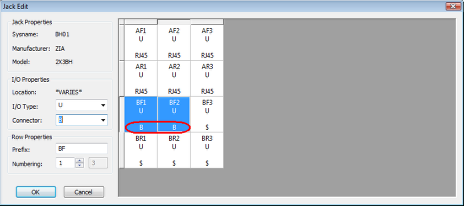
28. Select the third position on the front of Row B and change the connector type to an XLR connector.
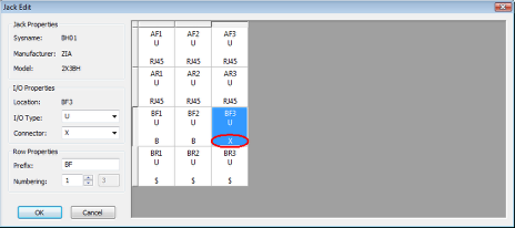
29. Change the connectors for the rear of Row B to match the image below.
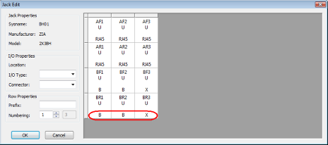
30. The jack definition should now look like the image below.
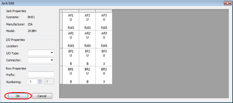
31. Select “Ok” to complete the modifications to your jack panel.
32. Select “Ok” to close the Select Jack window.
33. Your bulkhead panel is now available for use during cable transmutation.