InterCONNECT Drawings Used Only Option
InterCONNECT drawings are a graphical report in VidCAD that extracts the InterCONNECT information about a single equipment item from the database and creates a diagram based on that information. The information is displayed as a drawing file at a location you specify and includes Sysname, signal, I/O, rack and cable information. When creating the InterCONNECT drawing, you must select which input and output to display a signal path for. Most users want to show only I/Os that have cables connected to them, and for equipment with many I/Os, it can be difficult to scroll through the list to select only the used inputs and outputs. To speed up the process the “Used Only” option allows you to bypass the I/O selection window and automatically select only the inputs and outputs that have cables connected to them.
The following procedure will show you how to create an InterCONNECT drawing using the “Used Only” option.
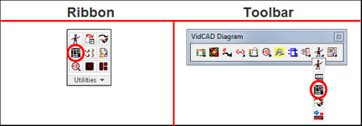
1. Select “InterCONNECT” from the VidCAD Utilities ribbon or toolbar
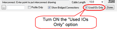
2. Check (turn on) the “Used IOs Only” option.
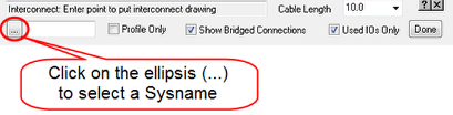
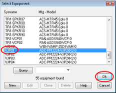
3. Select the Sysname Query ellipsis(…) button.
4. Select the Sysname of the equipment you want to create an InterCONNECT drawing from and select “Ok.”
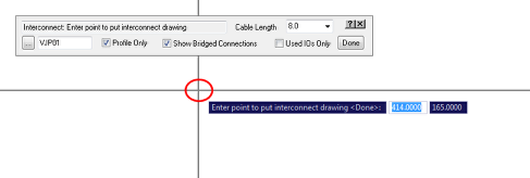
5. Select an insertion point for the InterCONNECT drawing.
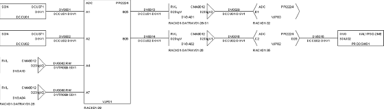
6. The InterCONNECT drawing now appears and, since the Used IOs Only option was selected, it shows the full signal path for each input and output that has a connection.

7. Press “Esc” on your keyboard to exit the InterCONNECT command.