InterCONNECT Drawings Full Path
InterCONNECT drawings are a graphical report in VidCAD that extracts the InterCONNECT information about a single equipment item from the database and creates a diagram based on that information. The information is displayed as a drawing file at a location you specify and includes Sysname, signal, I/O, rack and cable information. When creating the InterCONNECT drawing, you can choose to let the drawing extend out as far as the signal path goes, or you can choose the Path Only option, and the InterCONNECT will only reach out one piece of equipment for each input or output you select.
The following procedure will show you how to create an InterCONNECT drawing with a full signal path.
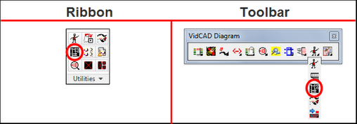
1. Select “InterCONNECT” from the VidCAD Utilities ribbon or toolbar.
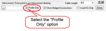
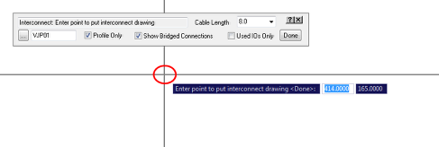
2. Uncheck (turn off) the “Profile Only” option.
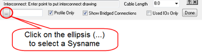
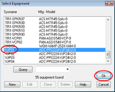
3. Select the Sysname Query ellipsis(…) button.
4. Select the Sysname of the equipment you want to create an InterCONNECT drawing from and select “Ok.”
5. Select an insertion point for the InterCONNECT drawing.
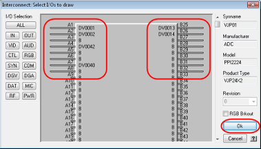
6. In the “Interconnect: Select I/Os to draw” window, select the inputs and outputs that you want to display.
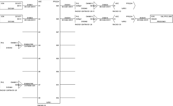
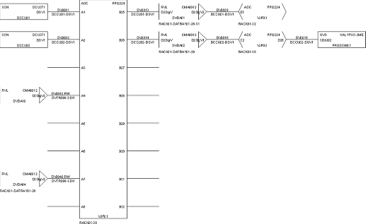
7. The InterCONNECT drawing now appears and, since the Profile Only option was NOT selected, shows the full signal path for each input and output selected.
8. Press “Esc” on your keyboard to exit the InterCONNECT command.