Editing Jack Panel Definitions
After adding a Jack Panel to your project, you can further customize the panel by changing the signal types, connectors, row definitions and numbering.
The following process will show you how to make basic changes to a jack panel definition.
1. Select “Phantom Cable Transmutate” from the VidCAD Cables ribbon or toolbar.
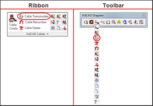
2. Select the “Jack” symbol from the Phantom Cable Transmutate window.
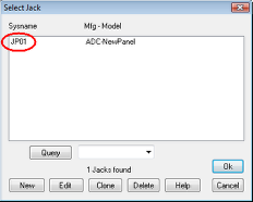
3. Select the jack you want to edit.
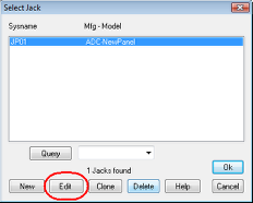
4. Select “Edit” in the Select Jack window.
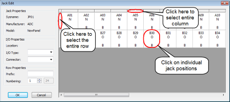
5. The Jack Edit window now displays.
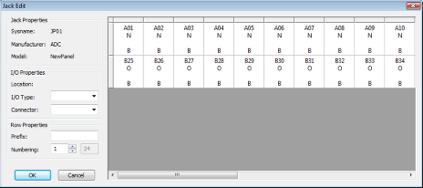
6. In the Jack Edit window, you can select rows, columns or individual positions to edit.
7. After you have selected the jack positions you want to edit, you will see the I/O properties can now be edited.
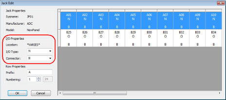
8. Change the definitions to meet your needs. In the image below, the top row connector type was changed to XLR and the I/O type was changed to Open. The bottom row was changed to a connector type of RJ45.
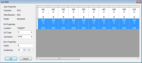
9. Select "Ok" to complete the modifications to your jack panel.
10. Select “Ok” to close the Select Jack window.
11. Your jack panel is now available for use during cable transmutation.