Creating a New Custom Jack Panel
You can create your own jack panel (aka: patch bay, patch panel, jack terminal, j-box, bulkhead) definitions using the following instructions. Once you create the definition, you can add it to any project.
1. Select “Phantom Cable Transmutate” from the VidCAD Cables ribbon or toolbar.
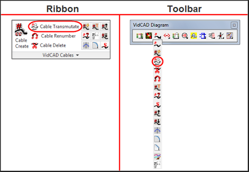
2. Select the jack symbol from the Phantom Cable Transmutate window.
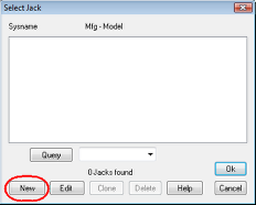
3. Select “New” in the Select Jack window.
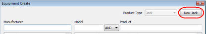
4. The Equipment Create window displays available jack panels that can be added to a project. To create a custom jack panel select “New Jack.”
5. Enter a model name, select a manufacturer, enter a product abbreviation and product description in the New Custom Panel window.
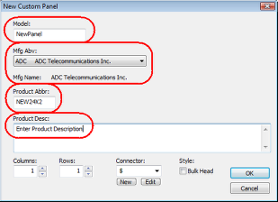
6. Define your columns and rows as well as the connector type.
Note: You can define the panel with up to 96 columns and up to 6 rows.
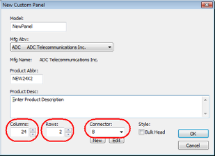
7. After all fields are entered, select “OK.”
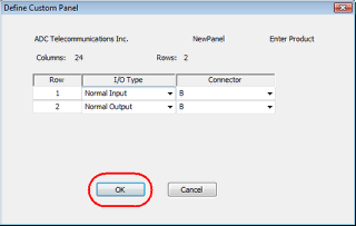
8. Select “OK” in the Define Custom Panel window.
9. You are now returned to the Equipment Create window.
10. Enter the Manufacturer and Model of the custom panel you created.
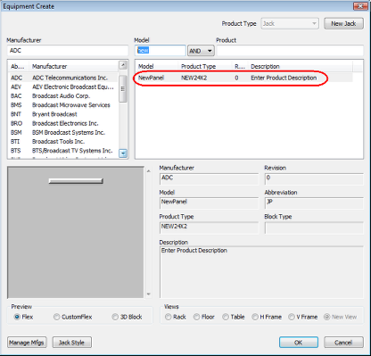
11. The New Jack Panel is now defined and part of your VidCAD library.
12. Select “Cancel” to return to your drawing, or select “OK” in the Equipment Create window to add a panel to your project.