Changing Router Symbols
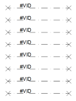
A router symbol represents a connection to a router without the need to have a router block in a drawing (which could take up much of your drawing space). VidCAD offers a wide variety of router symbols to allow you to customize your drawing style to your individual taste and needs. However, you can only use one style in a drawing. A collection of folders within the terminal sub-folder contains the various symbols. Examples of each of the styles are listed below with the corresponding folder name.
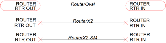
The default router symbol for ANSI or ISO drawing styles is “Router X2,” which is the center symbol on the image above. The most popular router symbol is the Router Oval, which is stored in the folder named “RouterOval.” To change the router style, follow these steps.
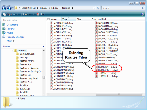
1. Use Windows Explorer to find your Terminal folder (C:\VidCAD\Library\terminal). In the Terminal folder, you will see two router drawing (.dwg) files. When you create a router in a VidCAD drawing, the program pulls the image from these files. In the following steps, you will overwrite these files with drawing files of the same name, but different router styles.
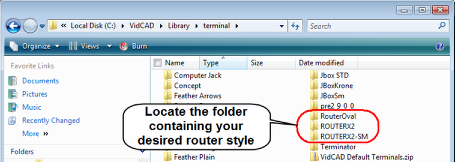
2. Locate the folder containing the router symbols you wish to use.
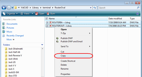
3. Open the desired folder and copy both drawing files.
4. Paste the files directly into the C:\VidCAD\Library\Terminal folder.
5. Select “Yes to All” when prompted to overwrite the existing files.
6. Open a VidCAD drawing and create a router to test for the new router style.
Note: If you are beginning a new drawing, your router style change is now complete. However, if you have already created routers in an existing VidCAD drawing, and wish to change the style, continue with the following sequence.
Purging Existing Router Symbols
If you have used another router symbol in a drawing before, you must AutoCAD/Bricscad Erase those symbols and purge the old router style block from the drawing. To erase and purge the old router block, follow these steps.
Note: These instructions are for drawings that have only a few router symbols. If you wish to replace many router symbols on a drawing, continue to the sequence of instructions on the following page.
1. Open the drawing containing the router symbols you wish to replace.
2. Erase all existing router symbols and associated cables from the drawing.
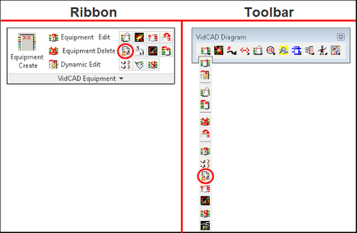
3. After you have removed all router symbols from the drawing, select “VidCAD Equipment Purge” from the VidCAD Equipment ribbon or toolbar.
4. The VidCAD Purge window now displays showing all equipment blocks (including routers) that have been erased from the drawing. Select “OK” to purge the old block definition.

5. Your drawing is now purged of any router symbols and any new router drawn will be your desired style.
Replacing Existing Router Symbols
If you have created many router symbols in a drawing, there is an easier method to replace them, instead of removing, purging, and redrawing all of them. In the following steps to replace feather symbols in a drawing, we will change all router symbols. Please note this example has both Router In and Router Out symbols.
1. Extract the desired router symbol into the terminal folder.
Note: In this example we are changing Router X2 symbols to Router Oval symbols.
2. Open the drawing with the router symbols you wish to replace.
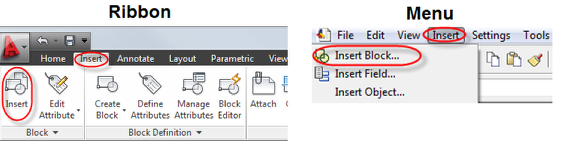
3. Select “Insert Block” from the Insert ribbon or menu.
4. In the Insert window, select “Browse…”
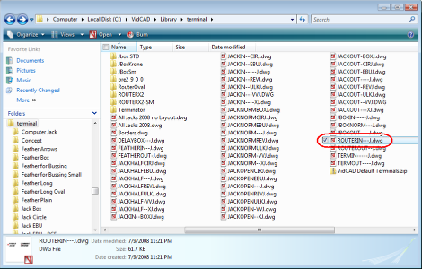
5. In the Select Drawing File window, navigate the “Look in:” field to your C:/VidCAD/Library/terminal folder. Then select the “ROUTERIN---J.dwg” file and select “Open.”
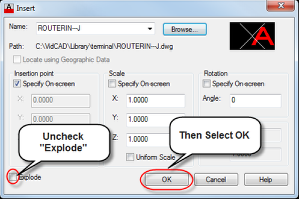
6. From the Insert window, uncheck “Explode,” then select “OK."
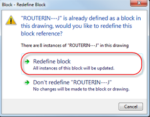
7. Select “Redefine block"” to update the definition of the existing “ROUTERIN---J” block references.
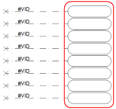
8. Your Router In symbols should immediately be redefined in the drawing. Press “Esc” to cancel the block insertion.
9. Repeat the process for the Router Out symbols.
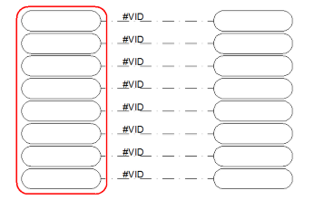
All router symbols are now changed to the desired style, and all future routers will have the desired router style as well.