Using the Router Border (AutoCAD Users)
A Router Border is used in VidCAD drawings to organize the look of multiple router I/Os. When documenting a large number of router inputs and outputs on a single drawing, you can use a Router Border to organize the router symbols and give them the look of a standard VidCAD equipment block.
The steps below will show you how to create a Router Border.
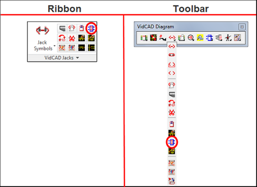
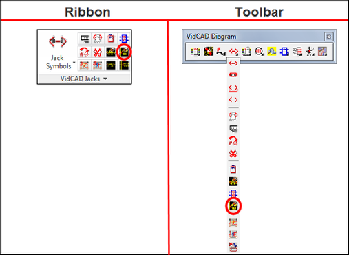
1. Select “Router Border” from the VidCAD Jacks ribbon or toolbar.
2. The command line will prompt you to specify an insertion point on your drawing. Click on the location you want to place the Router Border.
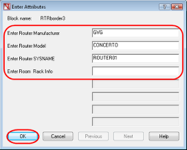
3. In the Edit Attributes window, enter a Manufacturer, Model, Sysname and Room/Rack information. Then select “OK.”
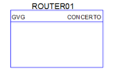
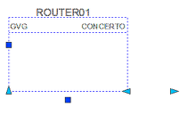
4. The Router Border should now display on your drawing.
5. Click anywhere on the Router Border to select it. You should see a series of grips and arrows appear.
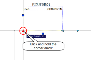
6. Click and hold the arrow at the bottom left corner of the Router Border and move your mouse down to stretch the Router Border.
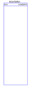
7. Press “Esc” and your Router Border should now appear with the desired length.
Note: The Router border can also be made wider by selecting the arrows near the bottom right of the block. A wider Router Border is sometimes necessary to accommodate longer Router Sysnames.
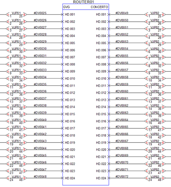
8. Move the Router Border to an existing series of router inputs and outputs, or draw new cables with the router symbols landing on or near the Router Border.
9. As an option to clean up the look of information in the router border, you can turn off the router Sysname to the inputs and outputs. To do this, select the “Router Sysname Off” command from the VidCAD Jacks ribbon or toolbar.
10. The Sysnames on the router symbols should now be turned off.
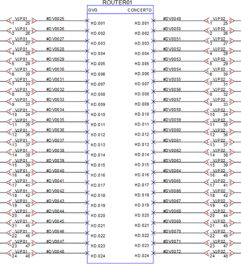
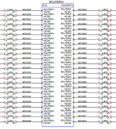
11. Notice the I/Os in the image above are slightly below the router symbol. If you will be frequently using Router Borders in conjunction with Router Sysname Off, we strongly recommend that you change your router style to the Router X2-SM style. See Section 11.5 of this manual for information on changing your router style.
12. The image below shows you the use of the Router Border with Router Sysname off and the Router X2-SM style in use.