Placing Phantom Non-Normal Jack Symbols
A jack/j-box symbol represents a single jack field position on a jack panel and is usually placed between source and destination equipment to allow manual routing of the signal. The jack symbol designates the jack panel system name, input and output row, and jack field position.
Jack types fall into three main categories: jack normal, jack half-normal, and jack non-normal. There are also single-ended jack symbols that represent just the input or output of a jack. J-box symbols can represent other terminal devices such as Telco, icon and bulkhead panels.
The following procedure will show you how to create a jack non-normal symbol.
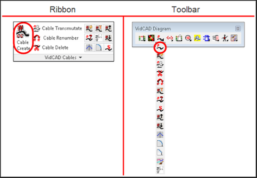
1. Select “Cable Create” from the VidCAD Cables ribbon or toolbar.
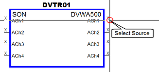
2. Select an output of the equipment block as the source of the cable.
3. Select the final destination on another piece of equipment to draw a cable.
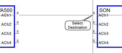
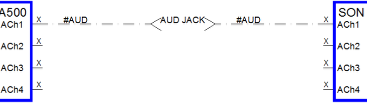
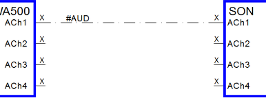
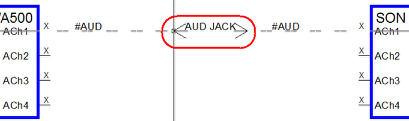
4. The phantom cable is now created between two pieces of equipment.
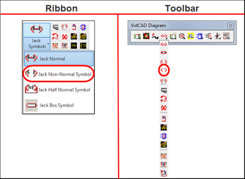
5. Select the "Jack Non-Normal" symbol from the VidCAD Jacks ribbon or toolbar.
6. A jack non-normal symbol now appears in your crosshairs.
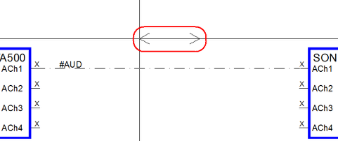
7. Place the symbol on your cable to insert it and split the phantom cable.
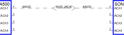
8. The cable with the jack non-normal symbol is now created.