I/O Type
When adding equipment to a drawing you have three style choices for the look of the inputs and outputs on an equipment block. This selection must be made prior to adding equipment to the drawing. The three I/O types are listed below, followed by instructions on how to change the I/O Type setting.
Type 1: Long
The long I/O type creates a fairly long (compared to the other two types) input or output. Notice for this I/O type the connector information is on the inside of the block and the line text is on the outside.
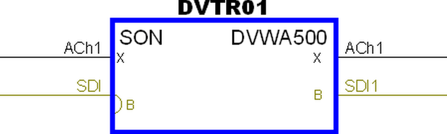
Type 2: Short
The short I/O type creates a short input or output. Notice for this I/O type the connector information is on the outside of the block and the line text is on the inside. The short I/O type is also the default type used in most VidCAD templates and the most popular among VidCAD users.
Type 3: Custom
The custom I/O type uses a .dwg icon to represent the connector on the equipment block. The icon that is used is defined when the connector is defined in VidCAD and can be modified. Notice for this I/O type the connector information and the line text are on the inside of the block.
The following procedure will show you how to change the I/O type on equipment flexiblocks.
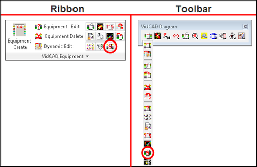
1. Select “Equipment Settings” from the VidCAD Equipment ribbon or toolbar.
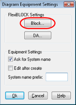
2. Select “Block” from the FlexiBLOCK Settings area of the Diagram Equipment Settings window.
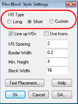
3. Select your desired I/O Type from the Flex Block Style Settings window.
4. Select “Ok” to complete the I/O Type change. All future equipment added to this drawing will use the I/O type you selected.