I/O Spacing
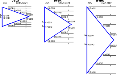
The I/O Spacing setting controls the vertical distance between inputs or outputs. The image below shows you the same DA with the same number of inputs and outputs, but with different I/O spacing. The first image has an I/O spacing of 1. The second has an I/O spacing of 2 (which is the default and used by the majority of VidCAD users). The final image has a spacing of 4.

The following procedure will show you how to change the I/O Spacing setting.
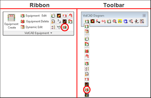
1. Select “Equipment Settings” from the VidCAD Equipment ribbon or toolbar.

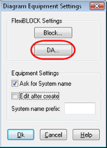
2. Select “DA” from the FlexiBLOCK Settings area of the Diagram Equipment Settings window.

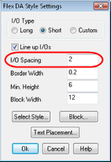
3. Change the I/O Spacing field as desired.

4. Select “Ok” and all future blocks added to this drawing will use this I/O Spacing setting.