Creating a Concept Drawing from the Sheet Set Manager
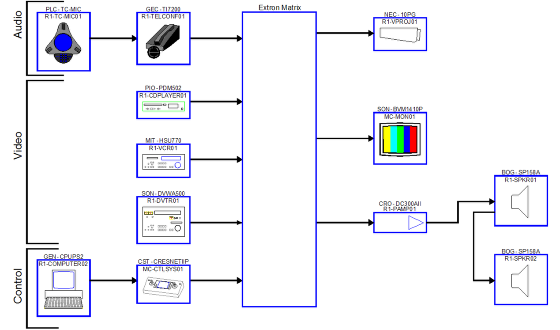
Concept drawings are high-level drawing files that demonstrate overall design. These drawings do not contain specific information about inputs and outputs. Concept drawings are usually used to prepare overviews for management or customers. Depending on your method of use, equipment placed in Concept drawings can be either phantom or real data, but because there is no input or output information on blocks created in concept drawings, cable information is only phantom. Specifically, VidCAD uses AutoCAD polylines in Concept drawings to show signal flow. Concept Drawings are created from the Concept Subset of the Room (Sheet Set Manager).
Note: Concept drawings do not display specific inputs and outputs. Use Diagram drawings to show input and output information.
1. Open the VidCAD Main Menu from the Start > Programs > VidCAD pulldown menu or your desktop icon.
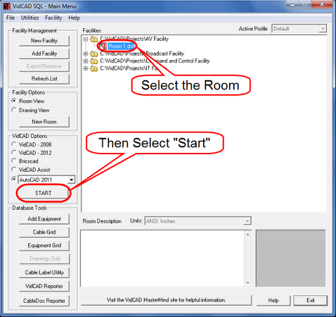
2. From the VidCAD Main Menu, select the Room in which you will create the Concept drawing, and then press “Start.”
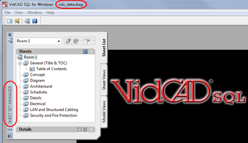
3. If this is the first time this Room has been opened, you will see a “vidc_data.dwg” file open with a Sheet Set Manager with your Room name. If it is not, skip to step 7.
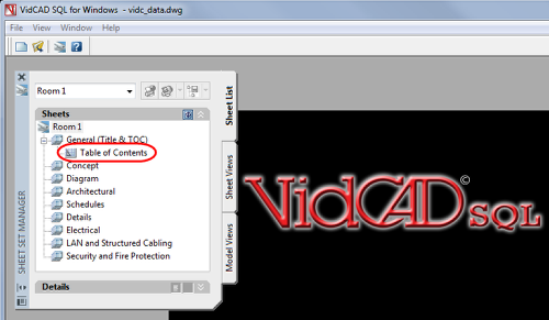
4. Double click the “Table of Contents” drawing to activate the Sheet Set (Room).
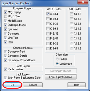
5. Select “Ok” in the Layer Diagram Controls window to finish opening the drawing.

6. Table of Contents drawing is opened with the name of the sheet set (Room 1) as the plotting tab name and a drawing with the same name listed on the main menu. When you open the Room in the future, this drawing will automatically open.
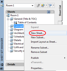
7. From the Sheet Set Manager, right click on the “Concept” subset and select “New Sheet.”
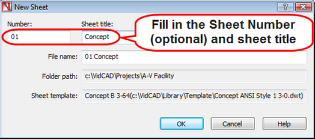
8. In the New Sheet window, enter the sheet number and sheet title, then select “OK.”
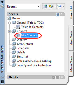
9. The new sheet now appears on the Sheet Set Manager.
Warning: You are not in your Concept drawing yet!
10. To open your new Concept drawing, double click on the “01-Concept” sheet on your Sheet Set Manager.
11. The Layer Diagram Controls window will now appear and list all available Safe Drawing Area Guides that match the paper size you can plot this drawing to. Select a guide and then select “Ok."
Note: Each Safe Drawing Area represents the maximum drawing area for a specific paper size in full size (3/64) and half size (3/32).
12. The Safe Drawing Area for the paper size you selected now displays.
13. Click the “Save” button. You are now ready to begin inserting equipment into your Concept drawing.