Adding DAs to a project
The process of drawing DAs in Phantom mode, then transmutating them to enter into the database can be bypassed by creating the DA in “Real” mode. Drawing in real mode creates the block in the drawing and enters its information into the database simultaneously. The procedure below will guide you through creating an equipment block in “Real” mode.
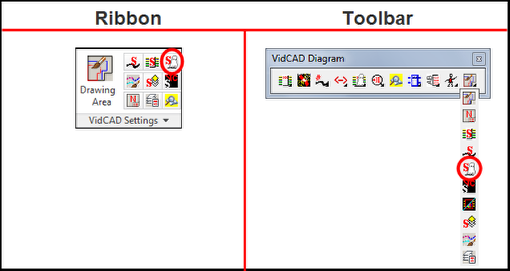
1. Select “Phantom Settings” from the VidCAD Settings ribbon or toolbar.
2. Uncheck “Phantom equipment active” then select “OK.”

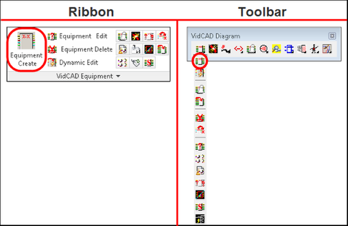
3. Select “Equipment Create” from the VidCAD Equipment ribbon or toolbar
4. In the Equipment Create window enter the Manufacturer and Model of the DA you want to add.
Note: You can also leave the fields blank to view the entire list of manufacturers or models.
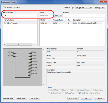
5. Select the desired model and revision from the list and select “OK.”
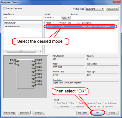
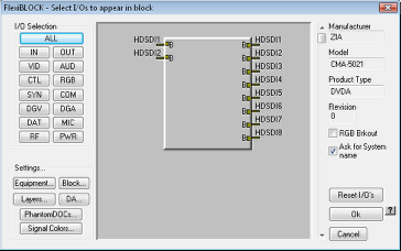
6. In the “FlexiBLOCK - Select I/Os to appear in block” window you can choose which inputs and outputs you want to display on your block.
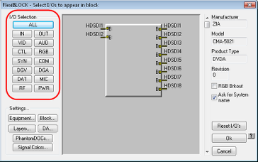
7. From the I/O Selection area, you can turn I/Os on by signal type, all inputs, or all outputs.
8. You can also turn I/Os on manually by clicking on the tip of the I/O.
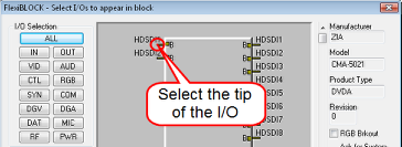
9. If you hold down your mouse button when selecting the tip of the I/O, you can drag your mouse up or down and activate multiple I/Os at once.
10. Experiment until you find a method you are comfortable with, then select all I/Os.
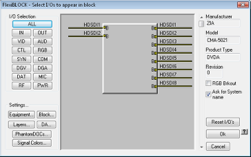
11. Select “Ok.”
12. Review the Select System Name information and select “Ok.”
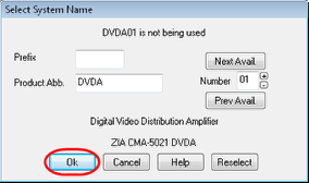
13. Select a point in the drawing to place the DA.
14. If you have “Edit After Create” active in your Equipment Settings the Edit Equipment window will now display.
15. Review the information in the Edit Equipment window and select “Ok.”
16. You are now returned to the Select System Name window and can continue to add the same models to the drawing by selecting “Ok” or you can select “Cancel” to exit the command or you can select “Reselect” to return to the Equipment Create window.
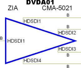
17. The DA is now added to your drawing and the database and is easily identified as real by its solid linetype.