2.9.1.101 -> 3.0.1.625
Summary of Changes for VidCAD SQL 3.0 (2.9.1.101 -> 3.0.1.625): April 30, 2010
There are over 144 new features, enhancements and corrections in this first version of VidCAD SQL 3. The top 58 customer-requested enhancements are highlighted in Bold.
Architectural Enhancements:
*Calculating cable lengths enhanced to provide more accurate lengths in mm or feet/inches, including:
-Cable lengths calculated for Multipair cables to the maximum length (e.g., if from bottom, to the top piece of equipment connected to the Multipair cable
-Accuracy enhanced by using 4 decimal points for conversions between ANSI and ISO
-Cable trays on or under floor
-Cable trays above or on the ceiling
-Conduits in walls
-Cable trays going any combination of above, below and the walls
*Corrected problems with old drawings for drop ceiling, walls and manipulating floors
BlueLine Equipment (BLE) and Cables (BLC):
*Work faster in BlueLine Cables and Equipment because unnecessary prompts and warnings are eliminated
*Full support for Feathers, Jacks, JBoxes and Routers, including Show/Hide BlueLine (SHB)
*Full support for Multipair, even down to which pair is deleted or restored
*Full support for bridged cables
*BlueLined equipment cannot be deleted with Equipment Delete (ED) or edited with Equipment Edit (EE) or Dynamic Edit (ER2)
*BlueLined cables cannot be deleted with Cable Delete (CD) or edited with Cable Edit (CE) or Dynamic Edit (ER2)
*BlueLined equipment and cables are Blue in Dynamic Edit (ER2), so you do not inadvertently try to edit it
*RedLined equipment does not appear in Delete/Restore BlueLine (DRB) dialog
*Equipment and cables cleared from Delete/Restore BlueLine dialog when BlueLine either accepted or restored
Show/Hide BlueLine shows status of equipment and cable changes, but only 1 instance needs to be marked for change to change Show/Hide status in all drawings
Cable Create Enhancements:
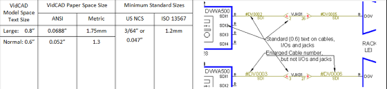
1. Cable Number Resize. Another top request is to be able to change the size of the text numbers. Cable numbers can now be sized up to 0.8” text height or downsized to 0.6” default.
Note: All other text remains the original size. Equipment, Jack and Router I/O data will remain the smaller size. Therefore, if you use this feature to condense more data into your plot, you will have extremely small text for I/O data (e.g., change Viewport Scaling from 1:12 to 1:16, your cable number will be 0.05” or 1.3mm, but your I/O and Feather/Jack text will be 0.036” or 0.93mm). Many printers will not even print this sizeand try specifying this size in your word processor! Here is an example of 2.5 point text: FYI: This is 2.5 pint text. This is 3 Point text. Would you like to read this consistently?
2. Cable Number Template saves whenever you move to the next cell. You do not need to remember to save each change!
3. In Concept, drawings now shows cable rubber-banding when placing terminals or drawing dog-legsyou will see the cable stretching as you drag
4. Jacks can be deleted from the Cable Create (Real Mode) or Phantom Cable Transmutate, when you go to the Jacks list (Jack … button). All associated cables are now deleted
5. Loop-thrus now are supported with feathers
6. In Real Mode, last selection of Feather, Jack and Router are automatically selected, thereby reducing the time to create real cables. Feather allows you to select from the whole equipment list, but last item is highlighted. Jack automatically goes to select I/O of Jack, but provides a drop-down for selecting another Jack
7. In Real Mode, corrected error where Jacks displayed incorrect Destination for cables bridged-in through Jack panels
8. Date of Creation (DOC) only on creation and Date of Edit (DOE) now updates on every edit (CE, Dynamic Edit (ER2), Cable Grid)
9. Multipair cables signal track thru all DAs
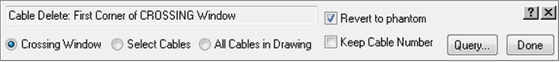
Cable Delete (CD) enhancements
New option for Revert to Phantom and not Keep Cable Number allows you to restore to original Phantom state (e.g., revert to #DGV instead of DV10933). This may make it faster if you repurpose the drawing in another facility or copy a room.
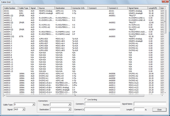
Editable Cable Grid added to VidCAD Main Menu
This provides:
1. Viewing Single and Multipair on a same grid view, which makes it easier to edit and review, and you do not need to change tabs between them.
2. You can now have Cable Grid or Equipment Grid live on your screen while you are editing your drawing, nice for editing on dual-screen systems.
3. In ISO projects, cable lengths shown in mm, in ANSI, shown in feet.
4. Cables can by dynamically sorted by clicking on any column label. For instance, if you want to work with all the cables terminating at ROUTER01, you would click on Destination and scroll to ROUTER01.
5. Live Sorting (dynamic sorting of the column you selected as you type) enables you to sort by Comments and enter a comment in a cable. As you enter Comment data, it will move the row to the appropriate location.
6. It supports multiple select, which allows you to select any cable groups then change the editable fields by typing in the data entry area.
7. It allows you to change cable types for single pair cables. Multipair cable type changes must be done in VidCAD, because the drawings and the database must simultaneously be changed (e.g., AA0001.BKR is in drawing).
8. Connectors are split into Source and Destination connectors for editing.
9. Only the editable fields are shown, so in the Multipair grid shown above, only Comment, Alternate (now relabeled Comment2) and Length fields. On the pairs, the Signal, Connectors and Signal Name are editable, but not Comment or Alternate (Comment2). All fields in edit area are editable in single pair cables.
10. All fields are checked for character length and compatibility as entered, and warnings are immediately given.
11. The new Cable Grid and Equipment Grid replace the old CableDOC Reporter Grid on VidCAD Main Menu
All changes are made instantly to the database, so they will be apparent inside VidCAD Cable Edit. However, in order for new cables to show in Cable Grid, you must close the grid and open again.
CableDOC Reporter enhancements:
1. Now available directly from CableDOC Reporter button in VidCAD toolbar.
2. All fields are exported in UPPER CASE, which improves report queries and sorting.
3. Eliminated duplicate equipment listings in Equipment Specs reports if there were multiple REV#s for that piece of equipment.
New Reporter in Beta
New web-based Reporter is in Beta right now. It will be released in a few months. Its benefits include:
1. Faster access to reports and labels.
2. Additional reports, including VidCAD Change Log.
3. Merging of multiple Equipment and Cable error reports into single report.
4. Multiple users can access Reporter at the same time.
5. Turn columns on/off with 1 click.
6. Modify language or column names easily and across all reports.
Easily modify table and header styles as well as currency symbols and date formats.
Drawing Settings have been simplified between ANSI and ISO, including:
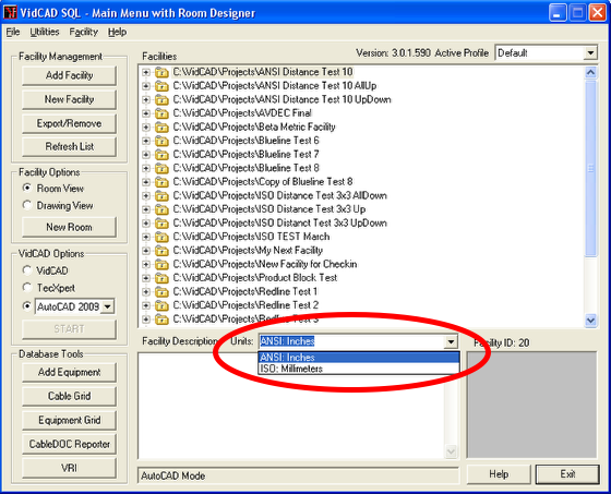
1. New VidCAD Main Menu setting for Facility Units. When you or create or edit a Facility, you will be prompted for the Units standard you want to use. VidCAD now supports ANSI (inches) or ISO (millimeters) in this menu. What these mean in AutoCAD terms are the following for all VidCAD drawings:
ANSI (Inches) settings
-Units (INSUNITS) Inches
-Source (INSUNITSDEFSOURCE) Inches
-Target (INSUNITSDEFTARGET) Inches
ISO (mm) settings
-Units (INSUNITS) mm
-Source (INSUNITSDEFSOURCE) Inches
-Target (INSUNITSDEFTARGET) mm
2. Consistent setup for all drawing types. In the past, diagram drawings were required to use Unspecified/Unitless settings, but in architectural drawings, you had to set the drawing Units property to mm or inches. This required you had to open the AutoCAD Options, User Preferences and set the Source content units to inches and the Target drawing units to mm or inches. Now, VidCAD automatically fixes the settings in . It follows the following rules for each drawing standard:
a. Source content units will always be set to Inches
b. If Target drawing units set to Inches, Units will be set to Inches
c. If Target drawing units set mm or cm, Units will be set to mm
d. If Target drawing units set to unitless, feet, miles, meters, etc, you will be prompted to select Inches (ANSI) or Millimeters (ISO)
3. Auto adjustment of blocks in diagram blocks. When diagram drawing is opened, all blocks, Jacks, Routers and Feathers are now automatically converted and saved in inches or mm. Subsequent blocks are also converted. In the past, all diagrams were Unitless, because there can be no meaningful scale for logical diagrams. Now, all blocks are automatically adjusted. This means that any blocks created in inches can be placed in an ISO diagram without rescaling from 25.4
4. Because of these changes, if you edit a Jack or other terminal diagram symbol in Unitless, inches or mm, it does not matter, because VidCAD will automatically size blocks to your desired units
5. In 3-D, AutoCAD automatically scales blocks created in other standards. But these changes will also eliminate the hassle of finding your drawing is in inches because you forgot to change sizes. It will then allow AutoCADs auto scaling to work optimally. However, if you find a model which does not scale properly, you can scale it to the appropriate size, then use VidCAD Explode Block/ReBlock to save it in your desired scale.
6. If you need to rescale your diagram from ANSI to ISO, just change your AutoCAD Source/Target drawing units, open the drawing and it is now in the new scale.
7. If you need to print in both ISO and ANSI formats for diagrams, the VidCAD templates automatically account for the scaling of text in each size.
8. VidCAD now supports #.###,## and #,###.## numbering formats for ProdSPEC list and cost fields
Equipment Create enhancements include:
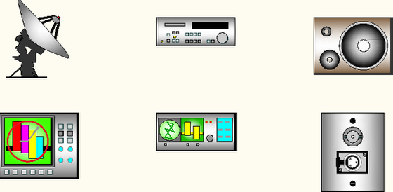
1. New Product Icons use shaded visual graphic style. These are especially nice for Concept drawings and for presentations. Here are a few examples:
2. In Edit I/Os, all digits are significant. This means, if you enter 001 to 9, the I/Os will be V001, V002, to V009. If you enter 1 to 11, it will be V01, V02…V11. This solves a major sorting issue which occurs in reporting because computers use ASCII sort (e.g., V10 and V11 come before V2).
3. New function in Copy or New allows you to create Furniture as well as equipment boxes or DA triangles.. If you select New or Copy Flex and you select Furniture button, you proceed to entering Product Specs, by-passing Edit I/O dialog box.
4. New option in Manage Flex to Add Revision, which allows you to keep the same model name and change I/Os. This functionality is imperative because manufacturers change I/Os without changing model name. This function requires you to enter a Revision Description (e.g., “Model delivered Jan 09 has HDMI instead of SVHS outputs”). This field appears at the bottom of the first Specs tab and now on the EC list. While this appears similar to previous use of REV#, you can still edit any REV# without automatically creating a new revision, plus you have the description to explain why you made a revision.
5. Conversely, if you Copy an existing model with a high REV#, VidCAD will restart the new REV# for new Model to 0.
6. Equipment Prefix now editable in Select System Name dialog.
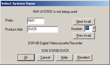
7. Equipment Prefix is also global for each user, accessible from EC and PET all drawings plus Add to List in EC and VidCAD Main Menu. Thus, if one engineer is working in room 103(R103-) and the other in room 215 (R215-), each can generate equipment with his own Equipment Prefix set to desired room.
8. In Manage Flex dialog, Box, DA, Furniture buttons are not editable on Manage Flex screen, as this is only a selection dialog. But you can edit them when you create a new model or copy another model.
9. If you incorrectly make a model as Furniture (which has no I/Os), you can add I/Os with Edit I/Osit then is changed to Equipment from Furniture.
10. When you change tab from Edit I/Os to Equipment Specs without creating any I/Os, you are asked if you want to create Furniture or return to editing I/Os. It is more efficient to create Furniture by selecting Furniture button, because it bypasses Edit I/Os.
11. All Furniture now has a REV# of *, which is essential for Dynamic Edit to differentiate between equipment and furniture. Improved selection of models by clearly distinguishing between Furniture (REV# =* with EQTYPE = 0 and IS2D = 0) and Equipment with FlexiBLOCKs (REV# = 0 to Z, EQTYPE = 1 and IS2D = 1). In the past, there were some models which did not appear on EC selection menu because these variables were not correct.
12. Scale of equipment icons in Diagram and Concept drawings have identical X, Y and Z scaling, so you can use Edit Block in Place (REFEDIT). For example, on a 16” standard diagram block, the old icons were scaled 8X, 8Y, 0Z, but now is 8,8,8.
13. Equipment Product icons now controlled by VidCAD Layer Settings Icon on/off button.
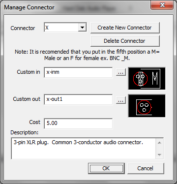
14. In Manage Connectors, an embedded viewer shows selected icons have view Source and Destination connectors.
15. When creating new or copying models, the expanded Mfg Abv box shows long list of manufacturers and full nameand you can continue to type to find the manufacturer you want.
16. Delete Many allows you to click on ascending or descending order by Model, Product Type or Equipment Type, making it faster to sort.
17. Delete Many will not allow you to delete equipment which is used in any facility, but Delete One will, with warnings.
18. 3-D Equipment Create/Equipment Recall more tightly controlled by PRODSPEC, so all dimensions are only entered once.
19. Furniture, Equipment Jacks and Routers all appear in 3-D Equipment Create dialog, so you can easily create 3-D view of all types of equipment.
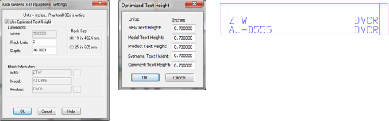
20. 3-D: Optimized Text Height allows you to specify the text height of 3-D attributes in ANSI or ISO sizes, so you can make drawing to meet your corporate, architect, customer or country drawing standard. For instance, if you want your equipment to always have 1” high text, you can specify this upon creation.
21. New equipment viewer added which allows AutoCAD 2008 and OEM to view equipment models in EC which were created in AutoCAD 2009.
22. Copy Model copies all specifications, icons and entries from donor item
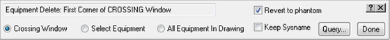
Equipment Delete enhancements include:
1. New option for Revert to Phantom which allows you to restore to Prodtype (e.g., revert to DVCR instead of R10-DVCR09). This may make it faster if you repurpose the drawing in another facility or copy a room.
2. Jacks and all associated cables can be deleted from all drawing types with Query. Warning: This can wipe out a lot of cablesespecially if you have selected setting to Delete Cables instead of Reverting to Phantoms.
3. Jacks can still be deleted from the Cable Create (Real Mode) or Phantom Cable Transmutate, when you go to the Jacks list (Jack … button). This function also removes all associated cables.
Equipment Grid replaces CableDOC Grid, Equipment, including:
1. Real-time saves of edits back to Equipment database, so you do not lose your place in the equipment list when you save, or worry about losing your changes because you forgot to press Save or from equipment failure.
2. Sort Equipment by SYSNAME, Mfg, Product Type, Room or Rack, which makes it easier to sort through a large list into meaningful subsetsjust click on the column name.
3. Meaningful field names make it easier to edit.
4. The list of fields for editing is pared to the essential ones used by customers. Others will be eliminated in next database change.
5. If you make changes in Equipment Grid, the changes are automatically saved to the VidCAD database, so are available inside VidCAD (e.g., for updating locations with Multi-Comment Edit (MCE). However, new equipment added in VidCAD will not be apparent until you close the grid and reopen.
6. If you make a hash of your edits, there is an Undo All button. Note that if you made changes in VidCAD with this data (e.g., MCE), these will not automatically be changed.

Equipment Dynamic Edit (ER2) enhancements
3 new classifications of equipment now included in list. These make it easier to visualize the whole status of you project in 1 place.
1. Equipment Listadded thru Add to List in VDPMM or Equipment Create but not placed on drawing.
2. Equipment Not in Drawingnot in any drawing for any reason (e.g., if equipment is erased from drawing but still in database).
3. Equipment Not in Rackequipment placed in diagram drawing but not in any rack or architectural drawing.
4. Also, logs are continually updated when these are added to a drawing, without running Refresh Log. However, if equipment is Not in Drawing because AutoCAD Erase was used to remove from drawings, VidCAD does not update the Refresh Log (RDCABLE and RDEQUIP). Only VidCAD commands change drawings and database objects simultaneously. In this case you will need to use Refresh Log (RL) command.
Equipment Explode Block (FX) and ReBlock (FB)
In 3-D, equipment can now be edited within the rack, or at any UCS setting. ReBlock remembers the UCS from the non-exploded block and creates the new block on
Equipment Purge (VEP) enhancements
VEP now deletes all unused blocks and layers, but does not delete Linetypes, Text, Multileader and Dimensional Styles, which are essential for VidCAD operations. This is much easier, faster and safer than AutoCAD Purge command.
Equipment Rename now supports Jacks
VidCAD v3 now fully support Renaming of jacks. You can also rename the row and column names in Jack Edit. NOTE: you should do this before creating cables, as cables will not be changed
Export/Import Facility enhancements include:
1. Added Export Report. This provides Equipment Models exported as well as cable types, Router types and project statistics such as cables, multi-pair cables, equipment pieces, Routers, Jacks and furniture that were successfully exported:
Note: If there are no errors or you export without library items, you will receive no warning.
2. Import improved to eliminate occasional duplication of I/Os
Facility Checkout/Checking (Platinum feature), greatly enhanced, including:
1. Checked-out facility only opens in Read-Only mode
2. If you have OEM, it gives you the option of opening Checked-out drawing in TecXpert
3. Tool tips for Facility data: Hold mouse over facility name to show who checked the project in or out and which Profile the facility originated and currently reside
4. When Facility is Checked-In, the original facility database is updated, new drawings are incorporated and the Read-Only locks are removed
Phantom Transmutate enhancements:
1. In Phantom Cable Transmutate, the last selection of Feather, Jack and Router are automatically selected, thereby reducing the time to create real cables. Feather allows you to select from the whole equipment list, but last item is highlighted. Jack automatically goes to select I/O of Jack, but provides a drop-down for selecting another Jack.
2. Corrected error where Jacks displayed incorrect Destination for cables bridged in cable attached to Jack panels.
3. Phantom Cable and Phantom Equipment Transmutate commands enhanced by removing prompt to Save to Phantoms Directory every time. This option still available on the toolbars, ribbons or menus.
RedLine (RLE and ARR) commands has been extensively rewritten so you can:
1. Work faster in creating Redlines because unnecessary prompts and warnings are eliminated
2. Full support for Feathers, Jacks and Routers
3. Full support for Multipair and bridged cables
4. RedLined equipment cannot be removed with Equipment Delete, which eliminates drawing errors
5. RedLined equipment appears Red in Dynamic Edit (ER2), so you do not inadvertently try to edit it
6. RedLined equipment cannot be edited with Equipment Edit or BlueLine Equipment
7. On acceptance, cables connected to changed equipment are updated both the connector info for the input and output connectors into the cable database
8. Signal name changes propagate down from the changed equipment, so if you changed from an Analog Audio to Digital signal, the signal type, signal color and signal name would change. It does not change the Cable Number to new signal type
9. Works with ANSI or ISO 3-D drawings, but all RedLine commands must be executed from Diagram drawing
Refresh Log (RL)
RL now deletes old RDCABLE and RDEQUIP records before recalculating the cables and equipment listed in every drawing. This removes all lost links so Dynamic Edit, RedLine, BlueLine and reports of all cables and equipment drawing reports are accurate. The only function not updating the record is AutoCAD Erase, since only VidCAD commands affect the database. That is why AutoCAD Erase is not recommended.
Microsoft SQL Server 2008 Express included
SQL Server 2008 is included instead of the Microsoft SQL Server 2005 Express or MSDE (the SQL Server 2000 express version).
VidCAD Main Menu Add Equipment to List enhanced, including:
1. Equipment Prefix added to Select System Name dialog, which is now globally stored
2. Support for adding Jacks and Routers
3. Support for defining furniture models and adding to the list
4. Viewer added for 3-D blocks, but only supports drawings created in AutoCAD 2007, 2008 or 2009. Older versions of blocks must be inserted in a drawing, then use Explode Block (FX) and ReBlock (FB)
5. Additional support for creating and editing equipment FlexiBLOCK definitions
Improved Connector create
VidCAD Main Menu improvements:
1. Cable Grid and Equipment Grid directly accessible, instead of going to CableDOC Gridand both are editable
2. New functionality to automatically transfer Country into Company Sheet Set address fields. When creating a new Sheet Set/Room, VidCAD now transfers the following information automatically to the Sheet Set Manager:
a. Customizable City/State/ZIP/Country data for company and clientboth transfer into Company Address3 or Client Address3
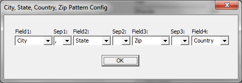
b. Client City, State, ZIP, and Country discrete fields are added automatically
c. Phone
d. Fax
e. URL
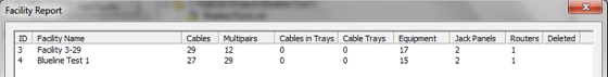
3. Facility Report has improved look and more descriptive headers
4. Facility Report shows total number of actual jack instances (not I/Os) and router (not number of levels)
5. Facility locked by Checkout/Checkin only opens drawings in Read-Only mode and offers OEM user opportunity to open in TecXpert or Read Only mode
6. Reset VidCAD Profiles now deletes old VIDC.CUI, making it easier to return to the original VidCAD state. It does not, however, delete the ACAD.CUI file, so it will not affect other drawing applications
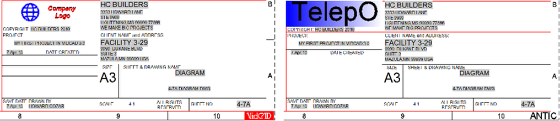
VidCAD drawing template enhancements include:
1. VidCAD logo in corner of Style 1, 2 and 3 templates is a separate block (My_Border_Logo.dwg for Styles 1 & 2, My_Border_Logo3 for Style 3), which can be modified externally and easily replace in your own templates similar to My_Company_Logo_Style block
2. New menu for updating your company, client and border logos, plus update your Template Title Blocks.

Use these tools to:
a. Put Client logo in your project and update logos based upon this client only
b. Support multiple Company logos
c. Update look and feel of Title Blocks then update templates with 1 click
3. New Import Title Block function for replacing Title Blocks in drawings from the Custom Title Blocks folder. This enables extensive customization of the Title Block and then using the 1-button ANSI or ISO version for your template style
The new "Default Facility and Template Settings" window provides more integration and automation to this process.
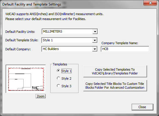
New Features include:
a. VidCAD remembers your Default Facility Units, Template Style and Company, so the next time you go to create a Room/Sheet Set, the default is chosen. For instance, on this example, the next Sheet Set template (.DST) would be HCB ISO Style 1 3-0.dst
b. VidCAD remembers your Company Template Name. This must be a name with no spaces and less than 15 characters
c. The option to Copy Selected Templates to your Template folder
The new option to Copy Selected Title Blocks from your Template\Title Blocks 3 subfolder
5. Add VidCAD\Library\Template\Custom Title Blocks folder where you can store all your customized Logos and Title Blocks. The Customize Templates tools automatically references this folder to update the Title Blocks for your style. Copy Title Blocks copies to this folder
6. To add custom Client Logos for each project, you can place the Client Logos in the Project. Then the Import Logo Style 2 or Style 3 will import that Logo into your drawings
7. Added descriptions to the VidCAD Layers. This makes it much easier to understand the plethora of VidCAD layers which are National CAD Standards compliant
8. Created new structure for creating your own templates using the Title Block Pieces. All attributes are included in the BASE drawings. So if you need to create a special sizesuch as ISO B, or a special look, you can create a new Title Block using the BASE drawing. Because all of the attributes are added in the correct order, it is easy to create any new look.
9. Added adequate borders for binding plots
10. Created a new DWF ePlot (optimized for plotting).PC3 file with VidCAD ANSI/ARCH Super B, D and E-sizes plus VidCAD ISO A1 and A0 sizes based upon the above binding area requirements. All Borders correctly fit at 1:1 scale within these sizes. This PC3 file is included in the dissemination of VidCAD v3
11. Discontinued using Expanded-size in all Title Block sizes, but used standard definitions for all other sizes besides those listed above
12. Eliminated problem with several fields with lost links to Sheet Set Manager
13. Super B format and D 3/32” templates included in Architectural sizes
14. Now dates and times are based upon date and time of creation of drawing, not template create date
15. Added the following Fields to the Sheet Set Templates (.DST):
a. Company Address3 (Uses data from the City/State/ZIP/Country configuration tool)
b. Project City, Project Country, Project Province, Project ZIP so has same fields as Company
16. Importing Company Address3, Project Address3, Company Phone and Fax, Project Phone and Fax into the Sheet Set
VidCAD TecXpert improved switching between TecXpert and VidCAD
Window 7 Compatibility
VidCAD installation now directly supports Windows 7 as well as Windows XP and Vista.
Note: if you have a Blue Hardlock key, you must call the VidCAD Sales team to review your options, as this will not work with Vista or Windows 7!