InterCONNECT Drawings Overview
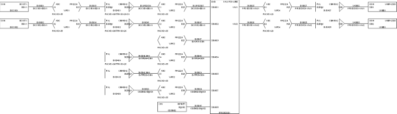
InterCONNECT drawings are a graphical report in VidCAD that extracts the InterCONNECT information about a single equipment item from the database and creates a diagram based on that information. The information is displayed as a drawing file at a location you specify and includes Sysname, signal, I/O, rack and cable information.
There are several rules and conditions that are important to know when using the InterCONNECT command.
1. The InterCONNECT is drawn based upon signal names (e.g., VTR01-V1). Signal names must be constant from the beginning of the circuit until the end.
a. Start at the source for transmutating cables. If you start at a DA, the DA output will be the signal name (VDA14-V2)
b. If Signal name was not constant, go to Cable Grid, select the cable numbers that should have contiguous signal names and copy & paste the correct signal name into the remaining cables.
2. The InterCONNECT does not branch except on the device chosen. e.g., a DA will only show the first output. You must select the DA to create the branching from it.
3. Only DAs and Jacks will confer a normal signal name through it. Other devices can be changed manually if needed.
4. In an InterCONNECT for a DA with multiple inputs, only the first in considered normal (as a pass through for signal name).